
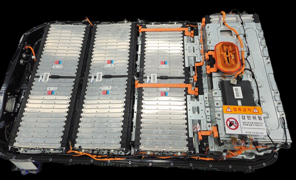
INPUT
Second-life battery pack
CMU, cell, sensor, and PRA data
Master Battery Management System
Fits the existing BMS location and collects cell/pack voltage, temperature, and sensor data.
Controls PRA and cell balancing, and links to BCMS in real time.
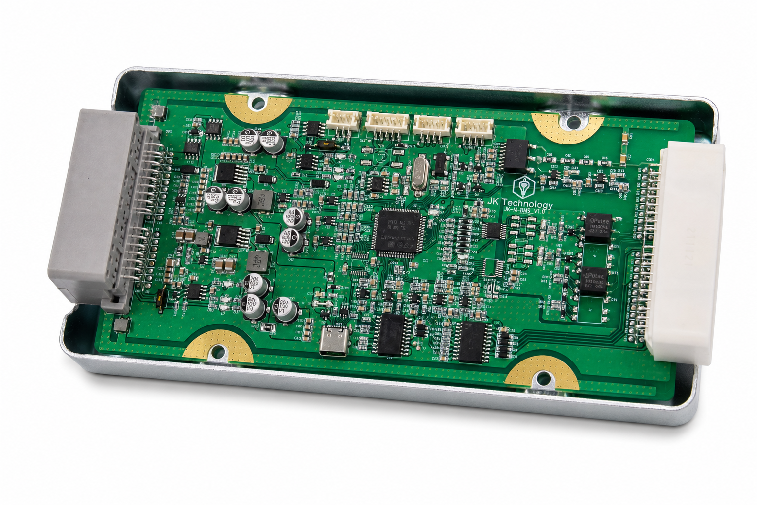
SIZE
189.5 × 94 mm
THICK
2.35 mm
COMM
UART
LINK
BCMS
01 · Characteristics
Existing BMS location · no cell/module teardown / bidirectional data and control · BCMS linkage
Mounts on pack-specific BMU connector and PIN MAP / matches vehicle communication specs.
PACK MATCHING
Links CMU, sensors, and PRA directly / obtains internal data without tearing down cells or modules.
DIRECT INTERFACE
Collects status and handles control commands / links PRA, balancing, and protection.
READ & CONTROL
Passes battery status, events, and control results / links diagnosis, alerts, and history.
BCMS LINKAGE
02 · Key Functions
Single-board M-BMS / collection, control, and data handling in one
03 · Integration
Collect pack internals and connect BCMS diagnosis, alerts, control, and history management.
INPUT
CMU, cell, sensor, and PRA data
Internal status data
INTERFACE
Protocol decode, data conversion, function control
Status/event transferControl command response
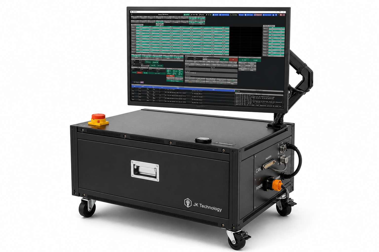
CONTROL & DIAGNOSIS
Diagnosis, alerts, control, and history
Screen/reportServer link
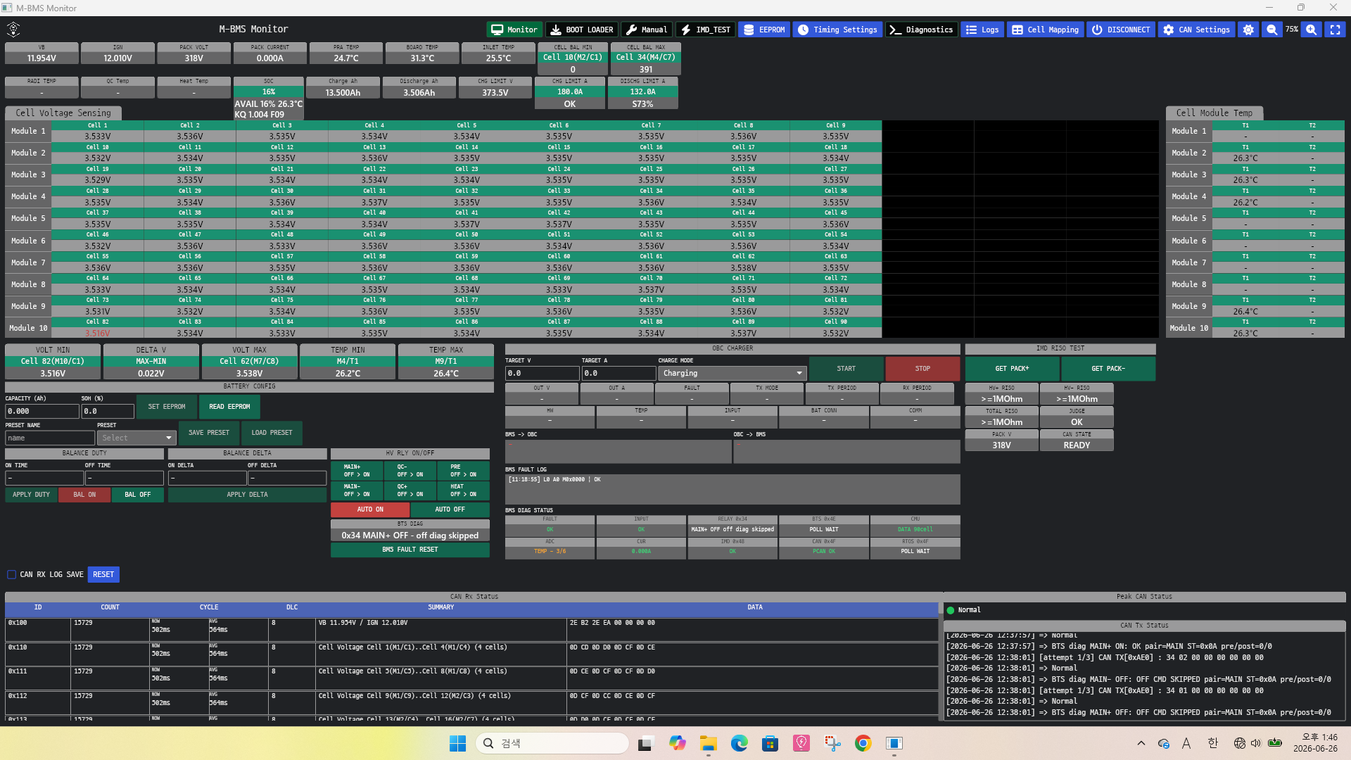
OPERATION
Field screen, remote data, external system link
INPUT
PROCESS
OUTPUT
04 · Specifications
PCB Thickness 2.35 mm · 189.5 × 94 mm
| Form factor | Board-type battery-pack interface |
|---|---|
| PCB size | 189.5 × 94 mm |
| Board thickness | 2.35 mm |
| Main inputs | CMU, cell, sensor, PIN, balancing status |
| Main outputs | Battery status, control results, events, BCMS data |
| Communication | 4-wired UART pack communication and BCMS link |
| Application | Pack-specific connector, PIN MAP, and protocol |
Communication specs and supported channels are configured to the applied battery pack.
We propose an interface configuration matched to your battery-pack specs and site environment.